

INTRODUCTION ::
Today the security is much important because of some worst kind of objects. Every one wants it weather if it is Bank,Govt.building,theatre,offices,or some
private homes etc. So we have selected the security system in our project.
We have selected the “Biometric sensor & Microcontroller based security system” earlier. But un-Fortunately the time limit was so short to get the biometric sensor because it is not available in INDIA
So then after we have chosen the punch card reader based security system based on Microcontroller. The Microcontroller works as the mind of the cir
-cuit system. It compares the data on the punched card & in itself ,then it
gives the respective output to the equipments placed on the output section
of the circuit.
The punched card is the main thing from which the controller identify the
person & to give response properly. If there will be positive response from
the controller the security system will be reduced by it else the alarm will
be highlighted. So no unauthorized person can enter over the security sys..
We have got the wide help from our Professors,internet,library etc. We
have made this project within three months.
PROJECT DETAIL ::
We have designed, developed & implemented security system using fundamentals of
match pair of IR Tx & Rx, manually made punch card ,electric lock & LCD for displaying the message. In future this can expand using memory card or biometric sensor
module.
The circuit diagram,description and relative topics are discussed as follows :
CIRCUIT DISCRIPTION ::
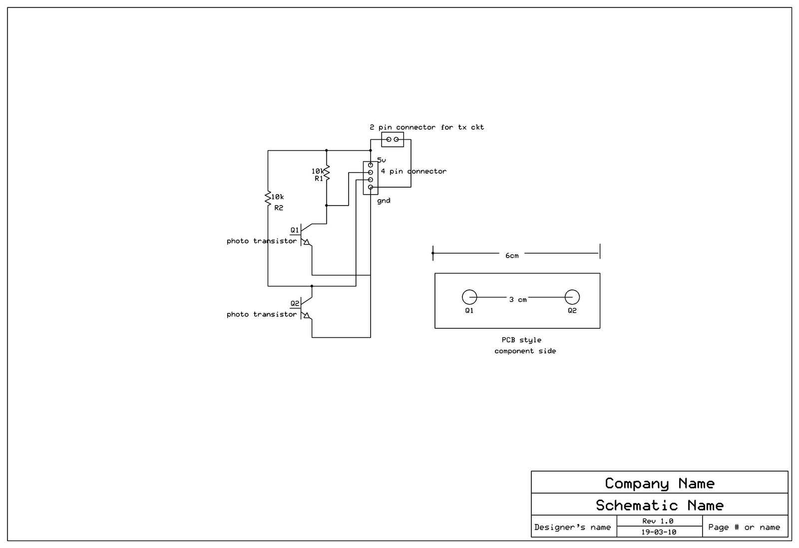
· In the above circuit of punched card reader, the main is IR transmitter & IR receiver. These two components makes the sensor for the card by placing both transmitter & receiver face to face on the horizontal plate. These portion of the circuit is combined in the box with the caution that the card can slip smoothly from the gap of the plate. This sensor works on +12v DC from the power supply & gives the output of about 5 to 8 volts.
· These output goes to the IC7414(NOT gate).Which gives the inverted linear
+5v to the controller pin 1,2,&3.These out put of 7414 is ANDed by 7410
IC (3-3 AND gate).This ANDed o/p is given to the pin 12,which is exter
-nal interrupt INTO.
· The controller works on +5v DC(pin 40 & 20).
· The crystal ckt. is on pin 18 & 19.it is 12MHz crystal.
· The port 0 is used for LCD display .Pin 21 & 22 of port 2 is used for the
out put. These o/p is given to the 8-pin relay via 2.7K resistors & transistor
CL100.
· The external pull up is on the port 0 through resister array of 10K & because it requires it.
· The electric lock & the green bulb are connected to relay 1 & the buzzer & the
red bulb are connected to relay 2. Lock & bulbs are operated on 230v AC &
buzzer uses +12v DC.
WORKING OF THE CIRCUIT ::
· This circuit works on the principle of match pair of IR transmitter & IR receiver.
· The card has the manually made punches(holes),which are the code for
the microcontroller.
· When the card is slipped in the plate of the IR Tx & Rx ,they gives the variation
in the voltage.when the hole comes the Rx becomes active high and gives 4 to 9v
DC to the IC7414(NOT gate).
· On the other side these o/p is also given to the pin INT0,the external interrupt,via

IC 7411.This is the 3 i/p AND gate.This is because to generate interrupt for micro-
-controller to read the data of the card`s holes.
· The o/p of IC 7414 goes to another i/p of the IC,& the second o/p is fed to the pin
P1.0 & P1.2 of the controller.
· When any hole comes across the sensor, the interrupt will be generated,& at the
same time microcontroller will read the data through pin P1.0. It will read the data
from the pin which the programmer has initialized in the program.
· Now the process starts of the program. If the code generated by the card is matched
to the data stored in microcontroller it will SET pin p2.0 on which the electric lock
is connected,otherwise it will SET pin P2.1on which the alarm is connected.
· The lock & the alarm are connected to microcontroller through resistor(2.7K),
transistor(CL100),& relay(8-pin).The relay also contains RED & GREEN lights
respectively.when the o/p pin is set the transistor conducts & the relay gets the
ground through transistor.
· At the same time of above procedure the LCD display also occurs. It displays the data stored in microcontroller.If the right card is inserted the name & comment
will be displayed otherwise warning will be displayed.
· The microcontroller works on the frequency of 6 to 15 MHz. The crystal circuit of
12MHz is connected on pin 18 & 19 which provides enough frequency to MC.
· Microcontroller also has facility of RESET.The reset circuit is on the pin 9.
which contains resistor & capacitor with +5v power supply & push switch. When
the switch is pressed the controller gets the +5v to get reset.
Indus
Indus
INDUSTRIAL UTILIZATIONS:
- We can use this product as a home security equipment replacing the bunch of keys upto unlimited users.
- also can be utilized as attendance feeding and reporting device
- We can widen its area of working by replacing cards to biometric sensor,retina scanner,face reader etc.
No comments:
Post a Comment